![]() #L17
#L17
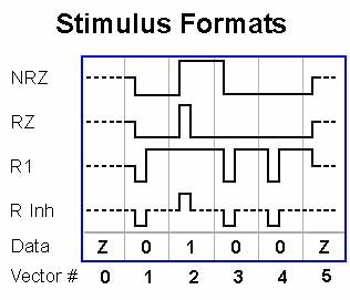
Q: What are the Stimulus Formats?
Stimulus Formats
|
When stimulus data is forced out to your DUT input pins it may need to be applied in a certain way. We already know, for example, that very often the data must be present at input pins before the clock edge occurs, allowing sufficient setup time. Stimulus formats help us to shape the stimulus data to conform it to follow the needs of your chip. You can select the stimulus for your inputs only in the Pin Setup window (F2). Here's a description of the different types of stimulus formats: NRZ stands for "Non Return to Zero". RZ means "Return to Zero". TT - TL meaning "trailing time minus leading time". If a zero appears then the output is unchanged for that vector. This format is commonly used for clocks, enables, strobes, and anywhere that control over both edges of stimulus is needed (dynamic data). R1 means "Return to One". |
R Inh is "Return to Inhibit".
Special Note on SCIO When you select Split Cycle I/O as your data direction and use NRZ as the Stimulus format, your expected data should always be the same as your stimulus data, or else masked when the ETS is driving. When your data is in the "Output" mode the ETS is not driving, and can capture the output of your DUT. But when the tester is driving, it is unlikely that your DUT's outputs will overcome the ETS drivers thereby making a compare only of the driver's state. When using any of the "Dynamic" formats, place your compare strobe away from the "pulse" created by your stimulus data. View your vectors in the Graph window to check your timing. Related info QL17.zip is a zipped Word file of this Q'nApp. Click your browser's Back button to return to the Q'nApps index. |