When connecting your DUT power pins to the ETS power supplies, several basic concepts should always be applied (or at least considered).
Here are some important considerations:
Power and Sense
The DUT power supplies inside of the ETS system provide programmable Vdd at the DUT board, as well as the sense lines for each supply. The sense lines are joined in surface etch on the DUT
board at the supply block and should be severed at this point to allow connection right at the DUT power pin(s). This is crucial for effective Iddq measurements. Be sure to polarize your supply; if you want positive voltage at the DUT pin, connect the Power supply minus to Ground on the DUT board. If you do not comply, your ground may "float" relative to the ground inside the tester, and thereby yield inaccurate parametric measurements.
Bypass Capacitors
You will need .01 and/or .1 uf bypass capacitors right at the power pins of the DUT chip socket for a local reservoir of power. Keep the leads as short as possible, and No Electrolytics! The farther your DUT is from the Power Supply, the more important are these capacitors.
Continuity
You may wish to create a SET file that includes the power and ground pins, solely for the purpose of checking continuity. These pins are typically connected directly to power and ground and do not get assigned to tester channels and so are excluded from continuity tests. Note: This applies only when power and ground pins are also connected to tester channels; custom DUT boards that do not connect power and ground pins to tester channels are N/A for this issue. Also, you may need to remove Power and Ground jumpers to give the ETS channel control over the DUT pin, just for the continuity test. For this reason, many forego continuity tests on Power and Ground pins.

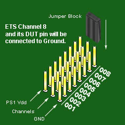 "Universal" Power and Ground Jumpering