Setting up for SCIO

Q:What is Split I/O?
Split Cycle I/O Data Format
The Split Cycle I/O mode (SCIO) allows you to switch data directionon every vector; that is within every vector. The typical applicationis to drive data to the DUT during the first part of each cycle and thencompare DUT output data during the second part of each cycle. Thismode also allows us to view the content of both the Stimulus RAM and theExpected Response RAM behind each tester channel.Setup of the Pin Group (F2 window) is represented in this example:
Setting up for SCIO
It is important to insure that you are not comparing Outputdata during the Stimulus portion of the cycle, otherwise you will be simplymonitoring the ETS pin driver, because your DUT output probably cannotovercome the 50 mA of drive current that the ETS driver is providing.When you now look at the Vector Edit window (F3) you can see two columnsof data for each pin. This data also shows Tristate and Mask information. Look at the following example:
Vectors Window using SCIO
For a better understanding of SCIO, it can be helpful to knowmore about the pin electronics memory. There are actually 5 RAMsbehind each ETS tester pin:Stimulus RAM (amber colored drive data)When a Tristate or Mask bit is set at any given vector, it does not meanthat the Stimulus or Response RAM is empty. Data is still presentin the Stimulus and Response RAM at every vector, we just cannot see thatdata when a Z or X is displayed. To see this data, simply place thecursor over the Z or X and type a U. You can also unmask or untristatean entire range of vectors by using a U with the Fill command.
Response RAM (blue Expected Response data)
Tristate RAM (an amber Z)
Mask RAM (a blue X)
Acquisition RAM (captures the DUT output in F4)If we look at the Vector Graph while the Vectors window is open, wecan see more about how the tester performs. Vector Graph can onlyshow Stimulus data in SCIO mode, but look at the following example to learnmore.
Vector Graph showing SCIO vectors
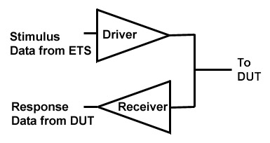
At HiLevel, we use SCIO to help verify tester functionalityby driving data on each pin directly into the pins receiver. This can be done entirely in software because of the design of the driver/receivercircuit:
Simplified drawing of ETS Driver/Receiver circuit
QL42.zip is a zipped Word file of this Q'nApp.
Click your browser's Back button to return tothe Q'nAppsindex.
© 2001 HILEVEL TechnologyInc.